

Headline: Pipe Dreams & Digital Schemes: Crafting Your Own Revit P&ID Library for Project Perfection!
Hey BIM trailblazers and design wizards! Ever stared at a complex P&ID diagram and wished your Revit model could just… understand it? You’re not alone! While Revit comes packed with amazing tools, sometimes, those generic pipes and fittings just don’t cut it when you’re dealing with the intricate world of Process & Instrumentation Diagrams.
That’s where the magic of creating your own custom P&ID pipe and fittings library swoops in! It might sound like a deep dive into the digital abyss, but trust me, it’s a journey that pays off in spades – think fewer clashes, clearer communication, and a whole lot less head-scratching.
So, grab your virtual hard hats, because we’re about to embark on a fun, informative quest to build your ultimate Revit P&ID arsenal!
Why Bother with a Custom Library? (Beyond Just Looking Cool)
Before we dive into the nitty-gritty, let’s answer the big question: Is it worth it? Absolutely!
- Accuracy is King (or Queen!): Generic families often lack the specific dimensions, materials, and connection data vital for accurate P&ID representation. A custom library means your model truly reflects your design intent.
- Clash Detection Nirvana: When your fittings actually “know” their size and connection types, Revit’s clash detection becomes a superpower, saving you headaches (and rework) down the line.
- Smart Scheduling & BOQs: Want to know exactly how many feet of Sch. 40 stainless steel pipe you need, or how many 2-inch gate valves? Custom parameters embedded in your families make quantity take-offs a breeze.
- Seamless P&ID Integration: Imagine your Revit model speaking the same language as your P&IDs – no more guesswork when linking data or tracking components.
- Project Consistency: A standardized library ensures everyone on your team is using the same, approved components, leading to a cohesive and professional model.
The Grand Adventure: Building Your Library, Step by Step!
Think of this as an epic quest with three main phases:
Phase 1: The Detective Work (Planning & Research)
Before you even open Revit, put on your detective hat!
- Project Blueprint: What pipes are we talking about? Carbon steel? PVC? What kind of valves? What level of detail do you need? This is your “shopping list” for the library.
- Manufacturer Manuals are Your Mates: Dig into those manufacturer catalogs! Get the precise dimensions, specifications, and connection details. This is your holy grail for accuracy.
- Revit’s Attic Search: Check what Revit already has. Sometimes, you can tweak existing families, saving you time. Don’t reinvent the wheel if you don’t have to!
- The Naming Game: Establish a super clear naming convention (e.g., “Pipe_CS_Sch40_DN150,” “Valve_Gate_Flanged_DN50”). This keeps your library organized and searchable – future you will thank you!
Phase 2: The Forge of Families (Creation & Customization)
Now, let’s get our hands dirty (digitally, of course!). This is where the magic happens!
- Starting Fresh (or Smart): Always begin with Revit’s generic “Pipe.rft” or “Pipe Fittings.rft” templates. They provide the fundamental framework.
- Geometric Guru: Model your components precisely using the manufacturer data. Every bend, every flange, every connection point needs to be spot-on.
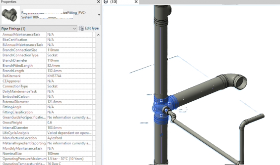
- Connector Commandos: This is critical! Add pipe connectors to every opening. Make sure their direction is correct (in/out), their flow configuration is set, and their system classification (e.g., “Hydronic Supply”) is spot on. This is how Revit “sees” your piping system!
- Parameter Power-Up:
- Built-in Buddies: Use Revit’s native parameters where they fit (like “Nominal Diameter”).
- Shared Parameter Superheroes: This is your secret weapon for P&ID integration! Create shared parameters for things like:
- P&ID Tag: The ultimate link to your diagrams!
- Material: Carbon steel? Stainless?
- Schedule/Pressure Class: Sch. 40? 150#?
- Manufacturer & Model: Who made it, and what’s its part number?
- And anything else specific to your project – the more data, the better!
- Decide if a parameter applies to every instance of a type (like material) or unique to each instance (like a P&ID tag).
- Type-Casting Time: For each family (e.g., “Elbow”), create multiple “types” for different sizes, schedules, or pressure classes. Think of it like a menu for your components!
- Nesting Niftyness (For Pros!): For super complex assemblies (like a valve with flanges and an actuator), consider “nesting” smaller families within a larger one. It’s like building with LEGOs!
- The Ultimate Test Drive: Load your newly minted families into a test project. Try connecting them, resizing them, and viewing them from all angles. Do they behave? Do they play nice with each other? Fix any tantrums they throw!
Phase 3: The Library Legacy (Organization & Management)
You’ve built your treasures; now, how do you keep them safe and accessible?
- Digital Dungeon Master (Folder Structure): Create a clear, logical folder structure for your families on your network or cloud platform. Think of it as your meticulously organized digital pantry.
- Template Tidiness: Load your most-used pipe types, systems, and routing preferences into your project template. This is your “quick start” guide for every new project.
- Documentation Dynasties: Write down your naming conventions, parameter definitions, and usage guidelines. This is your “secret scroll” for your team.
- Version Vigilance: Implement a system to track changes and versions of your families. No one wants to accidentally use an outdated component!
- Team Training Triumphs: Show your team the ropes! A beautiful library is useless if no one knows how to use it effectively.
- Maintenance Missions: Libraries aren’t static! Periodically review and update them based on new projects, new manufacturer data, or evolving standards.
And There You Have It!
Creating a custom P&ID pipe and fittings library in Revit is an investment, but it’s an investment that pays dividends in accuracy, efficiency, and a truly intelligent BIM model. It transforms your Revit model from just a 3D representation into a rich, data-driven replica of your P&ID.
So, go forth, design warriors, and craft your magnificent Revit libraries! May your pipe runs be smooth, your clashes be non-existent, and your P&ID tags always be accurate!
What’s your biggest challenge when working with P&IDs in Revit? Share your thoughts in the comments below!
![]()
Process for Creating a P&ID Pipe and Fittings Library in Autodesk Revit
Creating a robust P&ID pipe and fittings library in Revit is crucial for accurate modeling, clash detection, and quantity take-offs. Here’s a step-by-step process:
Phase 1: Planning and Research
-
Define Project Requirements:
-
Scope: What types of pipes (e.g., carbon steel, stainless steel, PVC), fittings (elbows, tees, reducers, valves), and specialty items (pumps, heat exchangers) are needed for this specific project?
-
Standards: Identify relevant industry standards (e.g., ASME B16.5 for flanges, B36.10M for pipes) and company standards.
-
Detail Level (LOD): Determine the required Level of Development (LOD) for the components. Will you need basic geometry (LOD 200), detailed geometry with connection data (LOD 300), or fabrication-ready models (LOD 400)?
-
Parameters: What information needs to be embedded in the families (e.g., material, schedule, pressure rating, manufacturer, part number, P&ID tag)?
-
Naming Convention: Establish a clear and consistent naming convention for families and types to ensure easy searching and organization.
-
-
Gather Manufacturer Data:
-
Obtain product catalogs, technical datasheets, and CAD files (if available) from the manufacturers whose products will be used in the project. This is crucial for accurate dimensions and specifications.
-
Look for existing Revit families provided by manufacturers. Sometimes, these can be a good starting point, though they often require modifications to meet project standards.
-
-
Review Existing Revit Content:
-
Check Revit’s out-of-the-box content. Some generic pipe and fitting families might be suitable for basic use, but they rarely meet the specific requirements of a detailed P&ID.
-
Review any existing in-house libraries or content from previous projects. Can any of it be reused or adapted?
-
Phase 2: Family Creation and Customization
-
Start with Generic Templates:
-
For pipes, use the “Pipe.rft” template.
-
For fittings, use the “Pipe Fittings.rft” or “Mechanical Equipment.rft” (for more complex components like valves or pumps) templates.
-
-
Model Geometry Accurately:
-
Dimensions: Use the manufacturer’s data to model the exact dimensions of the components. Pay close attention to connection points, lengths, and angles.
-
Connectors: This is critical for pipe and fitting families.
-
Pipe Connectors: Add pipe connectors to all connection points.
-
Direction: Ensure the connector direction is correct (inflow/outflow).
-
Flow Configuration: Set flow configuration (e.g., “Preset,” “Calculated”).
-
System Classification: Assign appropriate system classifications (e.g., “Hydronic Supply,” “Domestic Cold Water”).
-
Loss Method/Coefficient: Define these for accurate system analysis if needed.
-
-
Visibility Parameters: Consider adding parameters to control the visibility of certain elements (e.g., bolt patterns on flanges, handle positions on valves) for different LODs or views.
-
Detail Levels: Create simplified geometry for Coarse and Medium detail levels to improve model performance.
-
-
Add Parameters:
-
Built-in Parameters: Utilize Revit’s built-in parameters where appropriate (e.g., “Nominal Diameter,” “Length”).
-
Shared Parameters: This is essential for project-wide consistency and scheduling. Create shared parameters for:
-
P&ID Tag
-
Material
-
Schedule/Pressure Class
-
Manufacturer
-
Model Number
-
Weight
-
Insulation Type/Thickness
-
Cost
-
Any other project-specific data.
-
-
Type vs. Instance Parameters: Determine whether a parameter should apply to all instances of a type (e.g., material for a specific pipe size) or be unique to each instance (e.g., P&ID tag).
-
-
Create Types:
-
For each family (e.g., “Elbow”), create multiple types representing different sizes, schedules, or pressure classes (e.g., “Elbow – 90deg – DN50 – Sch40,” “Elbow – 90deg – DN100 – Sch80”).
-
Populate the parameters for each type with accurate data.
-
-
Nest Components (Optional but Recommended):
-
For complex assemblies (e.g., flanged valves, control valve stations), consider nesting individual component families (valve body, flanges, actuators) into a host family. This allows for better control and reusability.
-
-
Test Families:
-
Load the created families into a test project.
-
Place them in various scenarios to ensure they connect correctly, resize as expected, and display properly in different views (plan, section, 3D).
-
Check for any errors or warnings during placement.
-
Phase 3: Library Organization and Management
-
Establish a Library Structure:
-
Create a logical folder structure on your network drive or BIM 360 for your Revit families (e.g., “Revit Libraries > Mechanical > Pipes & Fittings > Carbon Steel > Valves”).
-
Categorize families by discipline, component type, material, or size range.
-
-
Create a Project Template:
-
Load frequently used pipe types, pipe systems, and routing preferences (e.g., preferred fitting types for specific pipe sizes) into your project template. This streamlines the modeling process.
-
-
Documentation:
-
Create a document outlining the library’s naming conventions, parameter definitions, usage guidelines, and any known limitations. This is crucial for team members.
-
-
Version Control:
-
Implement a system for managing revisions of families. Use clear version numbers and track changes.
-
-
Training:
-
Provide training to your project team on how to use the new library effectively, including best practices for modeling and parameter entry.
-
-
Maintenance and Updates:
-
Regularly review and update the library based on project feedback, new manufacturer data, or evolving industry standards.
-
Leave A Comment