
Creating a robust Revit family for a VAV (Variable Air Volume) unit, complete with system connectors, is a lot like an episode of Family Guy. It starts with a simple idea, quickly gets complicated with unexpected twists, and if you’re not careful, you might end up with a chicken fight of errors. But fear not, we’ll navigate this with the strategic brilliance of Stewie, the everyman charm of Peter, and the surprisingly insightful wisdom of Brian.

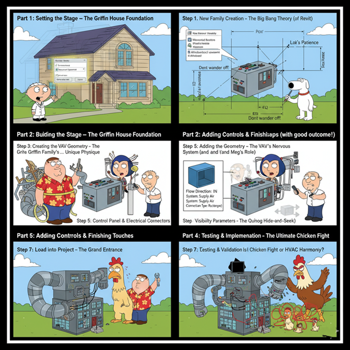
Part 1: Setting the Stage – The Griffin House Foundation
Just like the Griffins’ house in Quahog, every Revit family needs a solid foundation. You wouldn’t start building without a blueprint, and you wouldn’t expect Peter to understand advanced physics, right?
Step 1: New Family Creation – The Big Bang Theory (of Revit)
First, we need to open Revit and create a new family. Think of this as the moment Stewie decides he’s going to invent a new device – full of potential, a little intimidating, but ultimately exciting.
- Go to File > New > Family.
- Choose the “Mechanical Equipment.rft” template. This is our canvas, perfectly prepped for HVAC goodness. Selecting the wrong template is like Peter trying to bake a cake with gasoline – disastrous.
Step 2: Defining Reference Planes – The Layout of Quahog
Reference planes are the backbone of your family. They’re like the streets and landmarks of Quahog, giving structure and points of reference for everything else. Without them, your VAV would be as lost as Chris in a library.
- In a plan view (e.g., “Ref. Level”), create several reference planes using the “Ref Plane” command (RP shortcut).
- Dimension these planes and add parameters to control the width and depth of your VAV. Think of these as our “Peter’s Girth” and “Lois’s Patience” parameters – they’ll define our VAV’s physical boundaries.
- Tip: Use “EQ” constraints to ensure your VAV is centered around the origin. This prevents it from wandering off like Brian after a few too many martinis.
- Go to a front/back elevation view and add reference planes for height. Add a height parameter. This is like setting the roofline of the Griffin house.
Part 2: Building the VAV – Peter’s Construction Mishaps (with a good outcome!)
Now we start building the actual VAV unit. This is where things can get a little clunky if you’re not careful, much like Peter trying to assemble IKEA furniture.
Step 3: Creating the VAV Geometry – The Griffin Family’s… Unique Physique
We’ll use extrusion to create the main body of the VAV.
- In a plan view, use the “Create > Extrusion” tool.
- Sketch a rectangle that locks to your width and depth reference planes.
- Set the extrusion start and end to align with your height reference planes in an elevation view.
- Add material parameters if you want to control the VAV’s appearance. This is like giving Peter a new Hawaiian shirt – a simple change, but it makes a difference.
Step 4: Adding Connectors – The VAV’s Nervous System (and Meg’s Role)
This is the crucial part for system integration. Connectors are how your VAV talks to the ductwork and electrical systems, much like how Meg tries (and usually fails) to connect with her family. But unlike Meg, our connectors will be effective!
Duct Connectors:
- Go to “Create > Duct Connector”.
- Place a connector on one face of your VAV body (the supply air inlet).
- Select the connector and set its properties:
- Flow Direction: “In”
- System Classification: “Supply Air”
- Flow Configuration: “Calculated” (or “Preset” if you know the flow upfront)
- Loss Method: “Coefficient” or “Specific Loss”
- Connection Type: “Rectangular” or “Round” (match your VAV’s actual connection)
- Link up dimensions to parameters, allowing them to be controlled by your VAV’s dimensions.
- Repeat for the supply air outlet, but set Flow Direction: “Out”.
Electrical Connector:
- Go to “Create > Electrical Connector”.
- Place it on the side where your electrical panel would be.
- Set its properties:
- System Type: “Power”
- Voltage: (e.g., 277V, 120V)
- Number of Poles: (e.g., 1, 2, 3)
- Apparent Load (VA): Link to a parameter for wattage. This is like tracking how many beers Peter has had – essential data!
Step 5: Adding Controls and Finishing Touches – Stewie’s Gadgets and Brian’s Wit
This is where we add the details that make our VAV truly intelligent, much like Stewie’s brilliant inventions or Brian’s occasional philosophical musings.
- Control Panel (Optional): You can add a small extrusion or void to represent the control panel.
- Visibility Parameters: For different types of VAVs (e.g., with or without reheat coils), you can add visibility parameters to geometry. This is like having different outfits for Brian – sometimes he’s sophisticated, sometimes he’s just a regular dog.
- Select the geometry, then in the Properties palette, click the small box next to “Visible” and create a new parameter.
Part 3: Testing & Implementation – The Ultimate Chicken Fight
Now that our VAV is built, it’s time to see if it stands up to scrutiny. This is the equivalent of Peter fighting the giant chicken – a chaotic, brutal, but ultimately necessary test of strength.
Step 6: Loading into a Project – The Grand Entrance
- Save your VAV family.
- Open a Revit project (or create a new one).
- From your family file, click “Load into Project”.
Step 7: Testing and Validation – Is it Chicken Fight or HVAC Harmony?
This is where we test our VAV to ensure all connectors are working correctly and the family behaves as expected.
- Place the VAV: Place an instance of your VAV family in a plan view.
- Connect Ducts:
- Draw some ductwork in your project.
- Try to connect the ductwork to your VAV’s supply air inlet and outlet. If the connectors are set up correctly, Revit should allow seamless connection. If not, it’s back to the family editor, just like Peter having to re-strategize his chicken fight.
- Check Flow: Select a section of duct connected to your VAV. The flow arrows should indicate the correct direction, and if you have flow parameters, they should be present.
- Connect Electrical:
- Draw an electrical circuit.
- Try to connect it to your VAV’s electrical connector.
- Check Panel Schedule: If connected, your VAV should appear in the electrical panel schedule, showing its load. This is like making sure all of Peter’s expenses are accounted for (a rare occurrence!).
- Parameter Testing: Select the VAV in the project and go to its instance or type properties. Try changing the width, depth, and height parameters. Does the geometry update correctly? This is like seeing if Peter can actually fit into that tiny car.
Common “Family Guy” Errors and How to Fix Them:
- “No, I told you to go there!” (Misaligned Connectors): If ducts or wires aren’t connecting, your connector might not be precisely on the face of your geometry, or its orientation is wrong. Go back to the family and adjust.
- “What the deuce?!” (Incorrect Flow Direction): If your air is going the wrong way, you likely set the flow direction (In/Out) incorrectly on your duct connectors.
- “Oh, this is worse than the time…” (Broken Parameters): If your VAV distorts when you change parameters, your geometry might not be properly locked to the reference planes, or your dimensions aren’t associated with the correct parameters.

Conclusion: Our VAV, A Shining Star of Quahog
Just like how every Family Guy episode, despite its insane detours, usually wraps up (mostly) intact, we’ve successfully created a functional VAV family! It’s been a journey of design, parameter wrangling, and connector placement, all while dodging the metaphorical giant chickens of Revit errors.
Now, your VAV is ready to bring efficient air distribution to any project, proudly standing alongside the likes of Stewie’s time machine and Brian’s… well, Brian’s consistent ability to get into trouble. Go forth and create, knowing your VAV is as robust and entertaining as a night with the Griffins!
![]()
Leave A Comment