
Many US States and communities have added low-distortion projected coordinate systems for use in infrastructure projects. While Autodesk Civil 3D and Map 3D contain many of them, it does not contain them all. In this post, we will walk through the creation of a custom projection and discuss how you can use and share it with others.
The process is fairly straight forward. The most dialog driven way is via Map 3D/Civil 3D Planning and Analysis Workspace. On the Map Setup Tab, there is a panel of commands relating to coordinate systems. You can use these tools to Set, View/Edit or Create coordinate systems. These icons are similar to using the commands MAPCSASSIGN, MAPCSLIBRARY, and MAPCSCREATE.
Let’s walk through an example of creating a low-distortion projected system for northwest Illinois. Illinois has a 33 zone coordinate system centered around each major community. In this example, we will focus on Zone 2 which is centered around Rockford. The techniques for this system can be used for any system you wish to create.
First I will require to find out the parameters for the system I wish to create. There are several sources. A common one I typically use is a website like https://epsg.io/. You can search for a particular code and get info on it. None of the formats it gives info in can be directly imported into Civil 3D, however. But we can read many of these to get the parameters we wish using the WKT or “Well Known Text” format, which is basically plain text. This is not the only site, I can often find these systems governmental GIS clearinghouse or DOT sites.
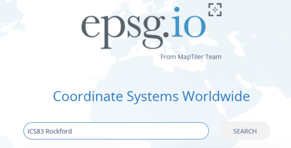
For the system in my example, I searched for “ICS Rockford” and found one hit.
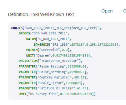
Selecting this, I can read the ESRI WKT format to see all the parameters I need to create this system in Civil 3D and Map 3D.
Let’s get started.
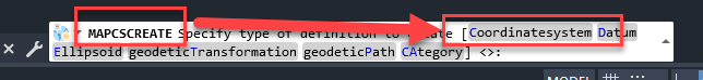
I will start by entering “MAPCSCREATE” in the command line of Civil 3D, and choosing the “Coordinatesystem” option.
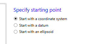
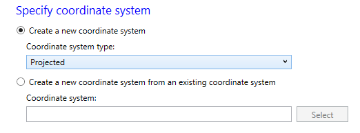
On the next page choose “Start with a coordinate system” and Next.
On the next, Coordinate system type “Projected” and Next.
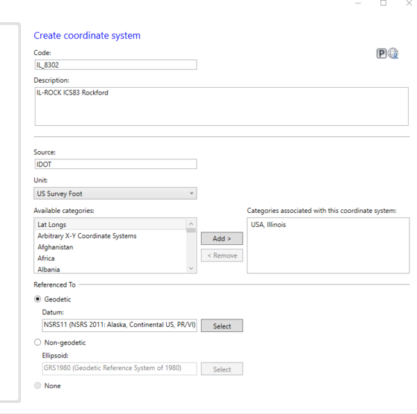
On the next page “Create Coordinate System”, I often fill in the “Code” section as the last step, as Civil 3D may crash if you fill it out first.
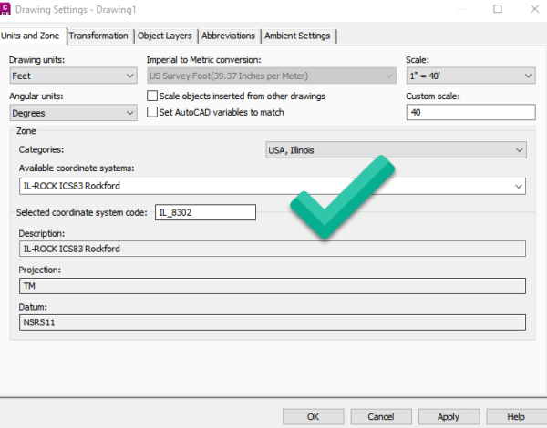
Create a Description, in our example: “IL-ROCK ICS83 Rockford”
Give it a Code: “IL_8302”
Source: “IDOT”
Unit: “US Survey Foot“
Category I will assign it to: “USA, Illinois”
Referenced to Geodetic: “NSRS11” which is equivalent to “GCS_NAD_1983_2011”. Next.
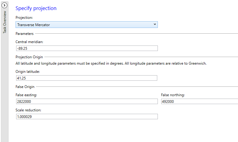
On the next page, fill out the parameters as shown below:
Projection: TM “Transverse Mercator“. You will get a message about changing projections, choose Yes and then we can fill out the form.
Central Meridian is in decimal degrees. West of the Prime Meridian it must be a negative number, so in our case we enter “-89.25” .
Origin Latitude is “41.25“. Again, this number would be negative south of the equator.
False Easting: “2822000“
False Northing: “492000“
Scale Reduction: “1.000029“
The next page is optional where you can enter descriptions for min and max valid limits plus some other descriptions. It will have no effect on your system if you leave it blank, but is a good idea to fill out if you have the information.
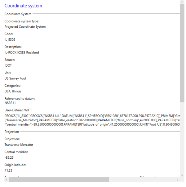
On the last page, you have a chance to review anything. If you need to fix something at this point, you can go back through and change what you need. Once you commit, your system will be created and you can use it immediately.
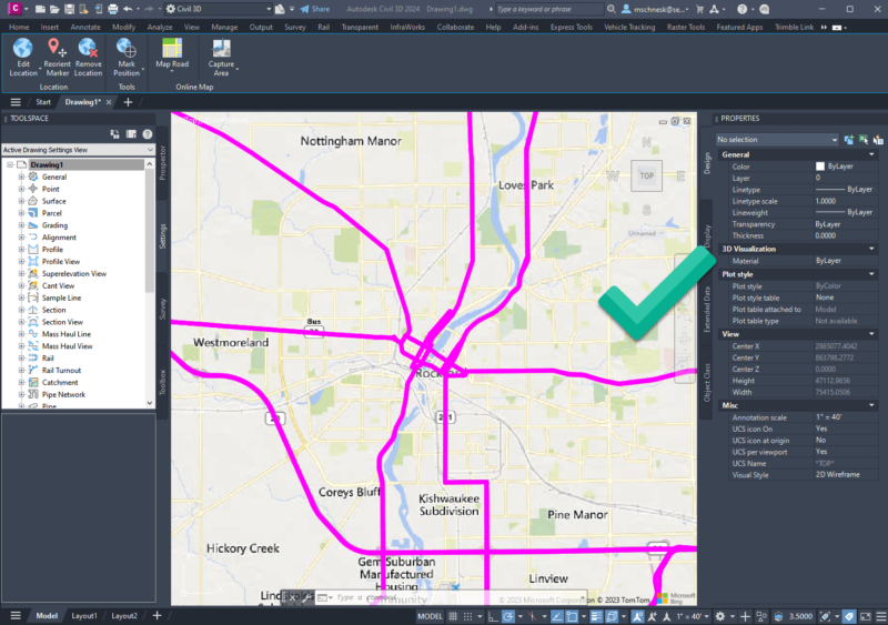
As a test, I set up a Civil 3D drawing using my new system and added my Bing maps background and some public data using the Autodesk Connector for ArcGIS Online. Success!
Some final notes:
If your system uses a Lambert Conic (LCC) projection, you would choose “Lambert Conformal Conic, single standard parallel” to allow input of an origin LAT/LON. But for any system that has a start and end LAT/LON, you would need to choose a double to enter a start and end for each.
If you need to edit one that may have an error, issue the command “MAPCSLIBRARY“. Find your system and choose the edit button. Make your corrections as per above and test it out.
If you wish to share your coordinate systems with other Civil 3D or Map 3D users, it is as simple as sharing a drawing that uses it. When another user opens this drawing they will have the option to add this to their library. Custom coordinate systems reside in “%localappdata%\Autodesk\User Geospatial Coordinate Systems” and can be copied/shared from there.
I hope this helps you along, and if you have any questions, please contact us at [email protected] or you may leave a comment below.
Have a wonderful day!
Leave A Comment