
In Civil 3D there is always more than one way to do just about everything! Reporting and gathering data for output is no exception. If you ever need to get the data in a presentable manner, both inside and outside of the drawing, here’s a few ways and tips on how to do so easily by creating reports in Civil 3D and other ways to view the data. Follow the steps outlined below in this blog or check out the video for even more details.
Pipe Network Data
Once you’ve created a Pipe Network, you have a multitude of ways you can look at that data. Today we’re taking a look at some of the functionality of the ways listed below to export that data:
- Pipe Network Vista
- Pipe Network Reports from Toolbox
- Pipe Network Tables
- Pipe Network Project Explorer Quick Report
Inside the Pipe Network you have both structures and pipes. When generating these reports make sure to include all of the needed parts of the Pipe Network to be represented in the report.
Steps to generate your reports:
1. Excel Report using Pipe Network Vista
- Head to the Ribbon, Modify Tab, Pipe Networks
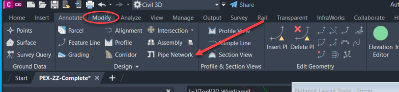
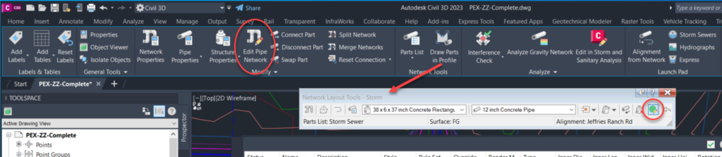
- Next select Pipe Network, which will bring up the Contextual Pipe Network ribbon, where you will select Edit Pipe Network and bring up the Network Layout Tools. Select the green circle tool button to bring up the Pipe Network Vista
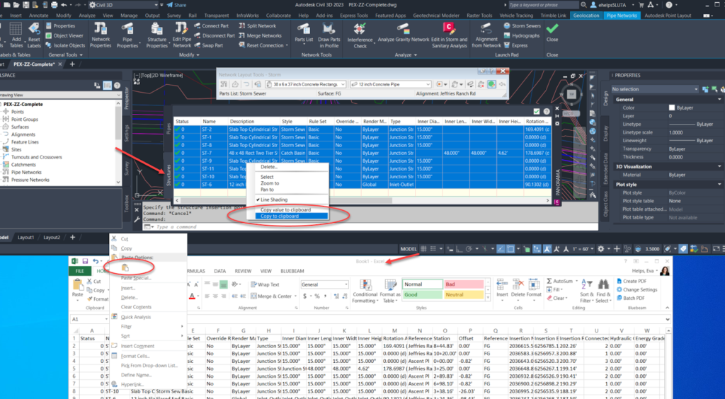
- From here Select all of the Structures on the Structures Tab of the Vista by selecting one, holding Shift on your keyboard and selecting the rest. Right click and Copy to Clipboard.
- Open a new excel spreadsheet. Right Click and Paste all of the information that was copied from the Pipe Network Vista Structures tab. Then repeat these steps for the Pipes tab within the Pipe Network Vista.
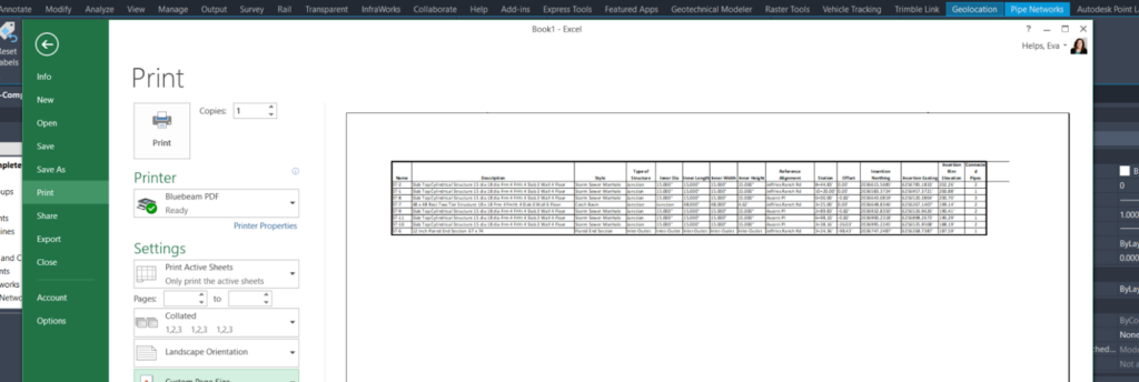
- Inside the new Excel Spreadsheet you can manipulate the text, columns, etc. to customize the report as you wish.
2. Tables to PDF
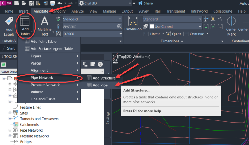
- On the Ribbon, go to the Annotate tab, Labels & Tables panel, Add Tables drop down, Pipe Network, Add Structures (or Add Pipes depending on which table is being created)
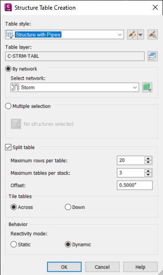
- The Structures Table Creation dialogue box will pop up.
- Select the Style of the table you are creating (the style will determine what information the table includes, and how it is displayed, then can edit this style or create a new one with the tool button to the right of the style selection).
- Next select the Pipe Network within the drawing (choose the pipe network that has the information needed for the table, choosing the green cube to the right of the pipe network selection will allow you to choose the network from a part within the drawing).
- Customize the table display with the options of rows, columns, and split.
- Choose to display the table as Static (a screen shot in time) or Dynamic (a smart table that will update automatically when the Pipe Network is updated in the drawing).
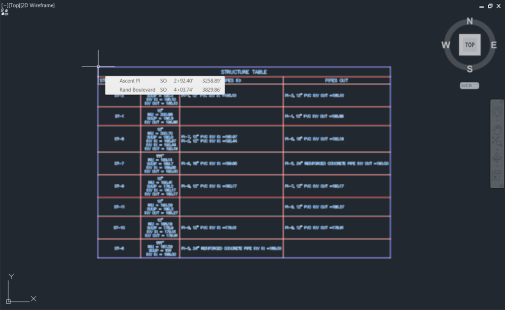
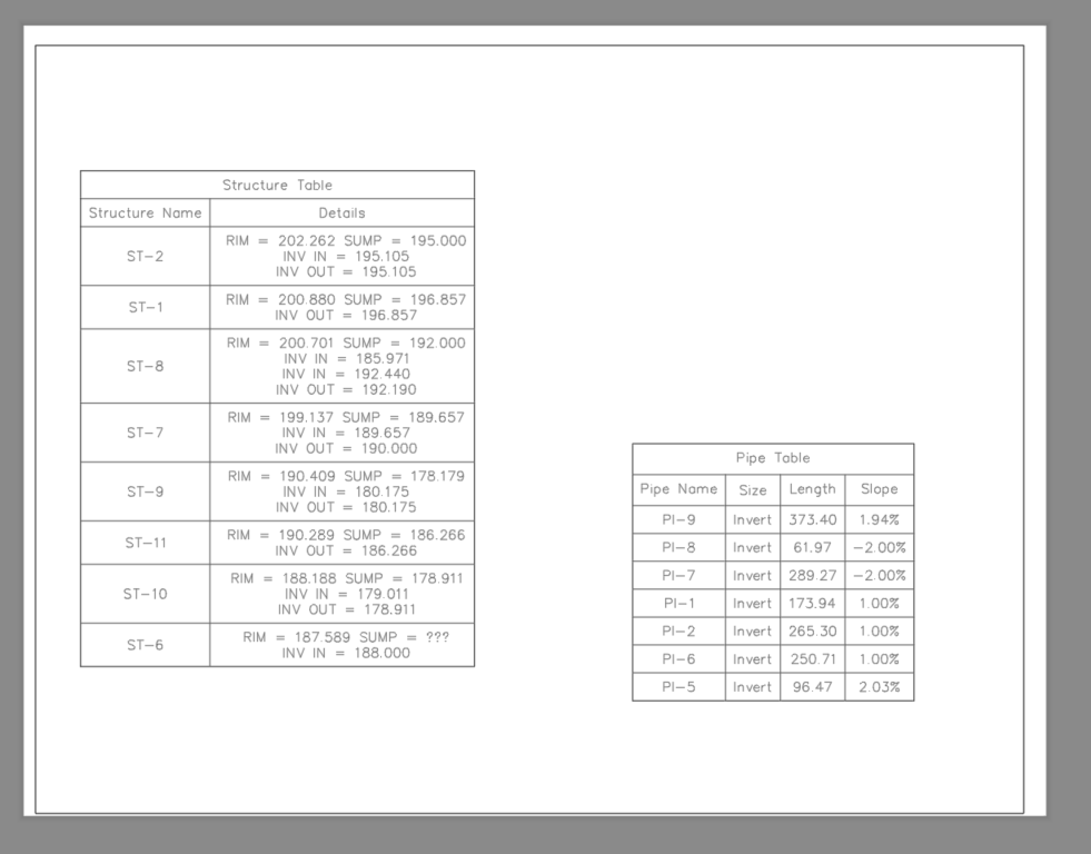
- Place the table in the drawing and repeat the steps for the Pipes
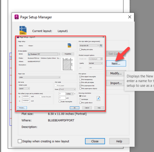
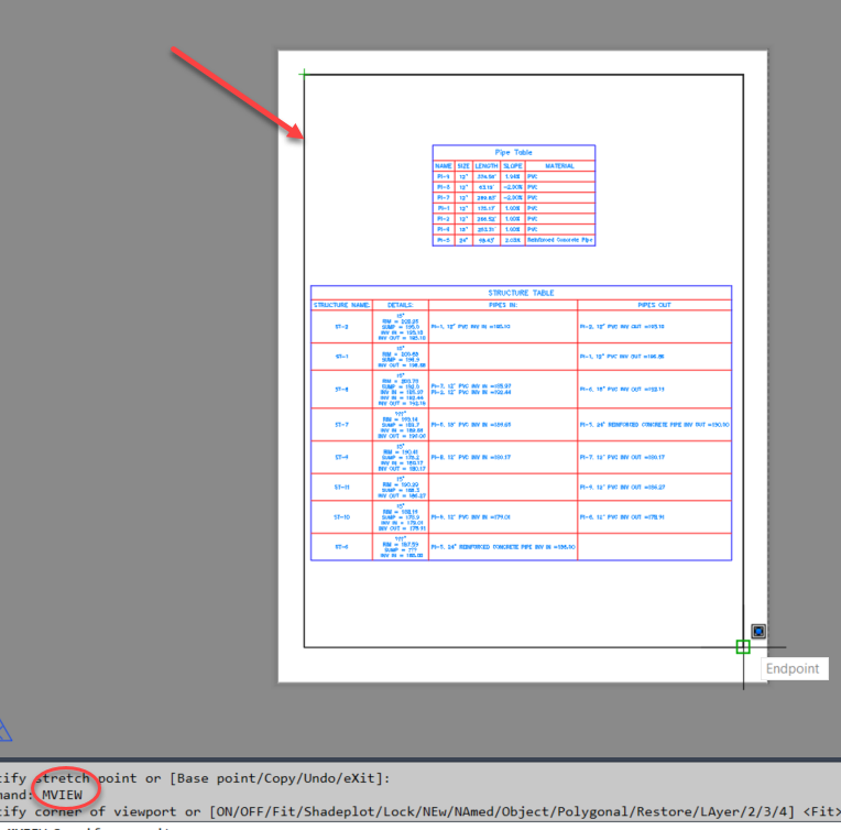
- Go a step further and create a pdf Layout of the Tables created by selecting a Layout tab, right clicking on the Layout tan and selecting page set up. Type in MVIEW to create a viewport for the tables, and print to PDF.
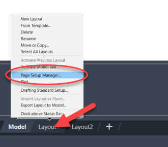
- Save the pdf print to a location inside the project for reference.
3. Pipe Reports using Toolbox
- To use the Reports Manager inside the ToolBox tab in Tool Space.
- On the Ribbon, Home Tab, Pallettes panel, ensure the Toolbox tab is highlighted blue. When highlighted blue, the Toolbox tab will then appear in the Toolspace.
- Select the Toolbox tab on the Toolspace. From here there is a toolbox icon in the upper right hand corner that allows customization of part of the report information and how it displays.
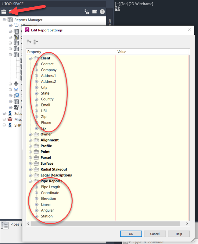
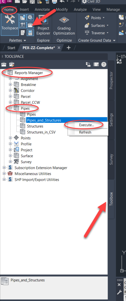
- To create a report for your Pipe Network, select Report Manager, Pipes and one of the report styles given by Civil 3D, in this case Pipes_and_Structures
- Right click on Pipes and Structures and select Execute. This will bring up the Export to XML Report window that allows the selection of the Civil Objects to include in report.
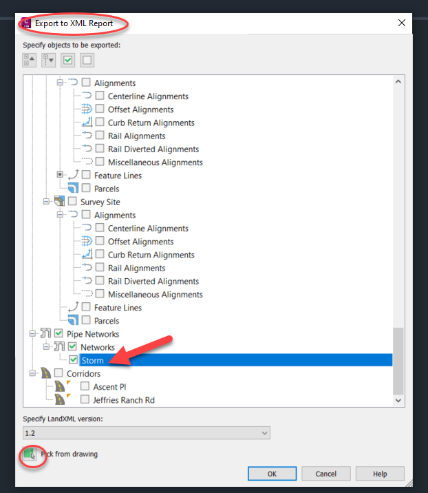
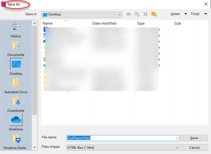
- Select the Pipe Network Storm or select the green cube to pick a part from the Pipe Network from the drawing and Select OK. Browse to where the file should be saved, name and save the XML Report.
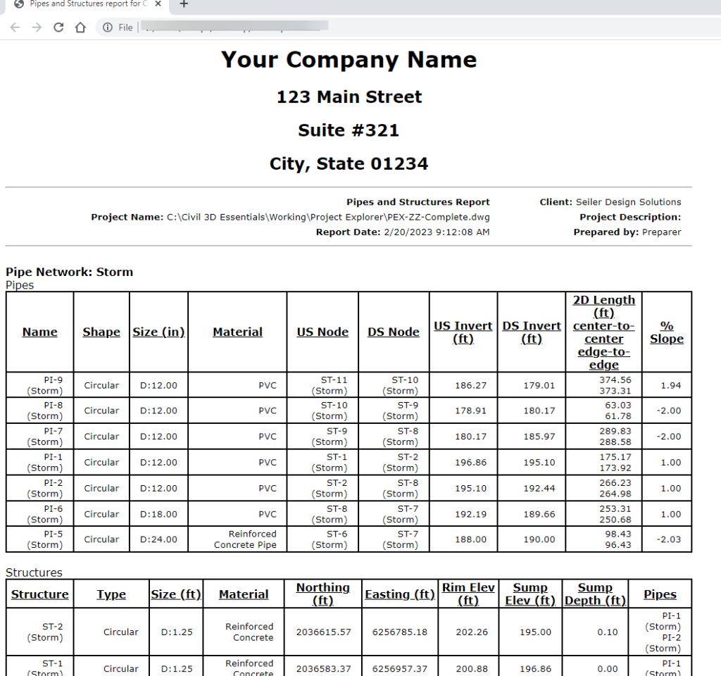
- A browser will pop up to view the created XML report.
4. Pipe Reports from Project Explorer
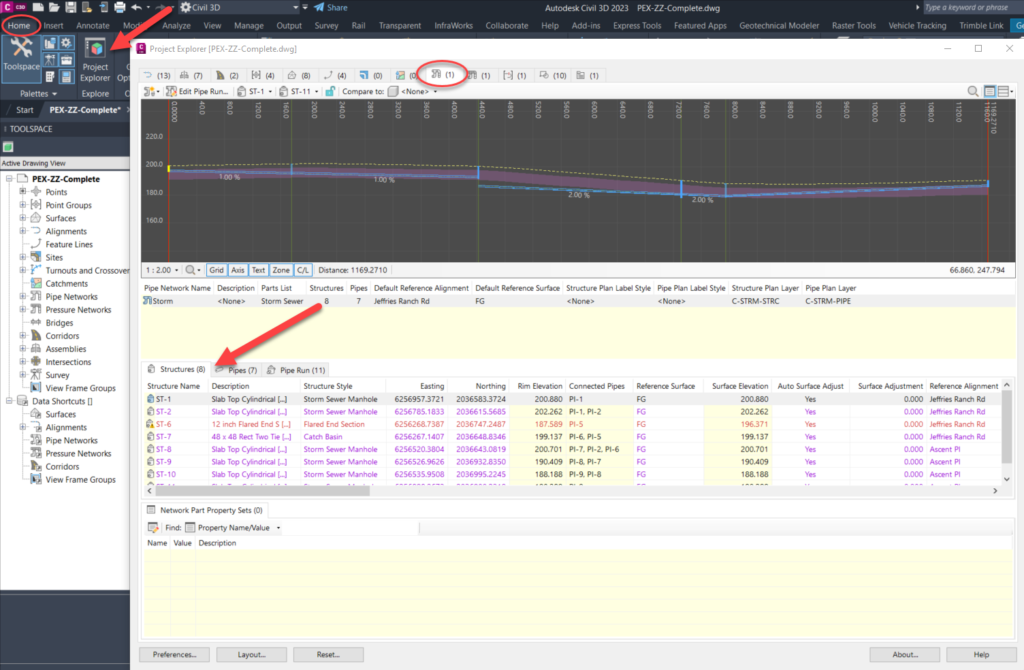
- Open up the Project Explorer from the Home tab on the Ribbon. Project Explorer is a one-stop-shop for managing and accessing all of the civil data inside the drawing (if you’re not familiar with the Project Explorer, check out our blog Intro to Civil 3D Project Explorer here)
- Across the top of the Project Explorer window are all of the civil objects you can view inside of it, including the Pipe Networks tab. Select the Pipe Networks Tab to view the Pipe Network Data in this drawing.
- How the Project Explorer window is set up and what it shows:
- Profile view of the pipe network
- Pipe Network information
- Structures, Pipes, and Pipe Run tabs with prospective information, some of which can be edited from this window
- Network Part Property Sets
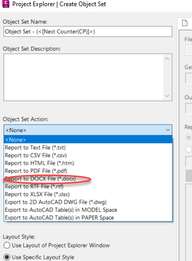
- To set up and customize a report, first set up an Object Set by selecting the tab at the far right, then selecting the New Object Set tool button.
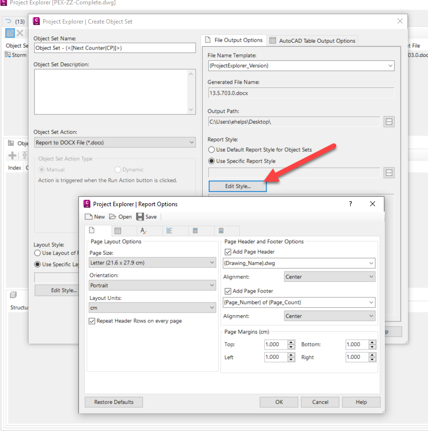
- Name the Object Set, select the type of output file for the Object Set.
- To customize the Layout, select Edit Style below at the bottom of the Create Object Set window. Select the Pipe Networks tab. Select the drop down arrow to choose the type of Object Data to change and customize by selecting the desired boxes with a green check.
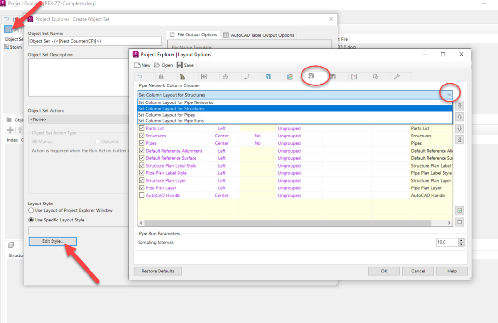
- Select the Edit Style button under the Report Style to customize the size, font, and look of the Report.
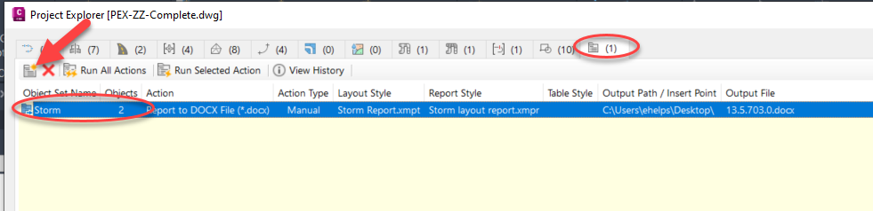
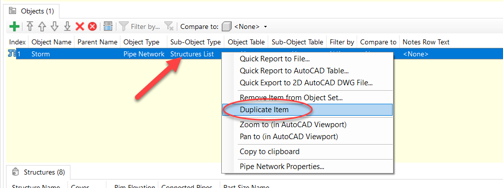
- Once an Object Set is created, Objects must be added to the set to generate a report. Select the green plus icon to add an object. Select the Pipe Network Tab, the Storm Network, and OK.

- A new Object appears including the Sub-Object Type-Structures list. Right Click on the Structures List and select Duplicate Item.
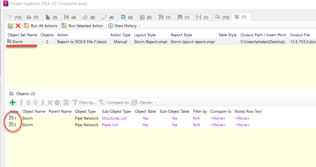
- To change the Sub-Object Type of the duplicated item, double click on the Structures List, choose the Pipes List from the drop down menu to change the Sub-Object Type to Pipes. (note: any item shown as magenta in Project Explorer can be edited easily within this window)

- There are now two Objects shown with the Object Set created.
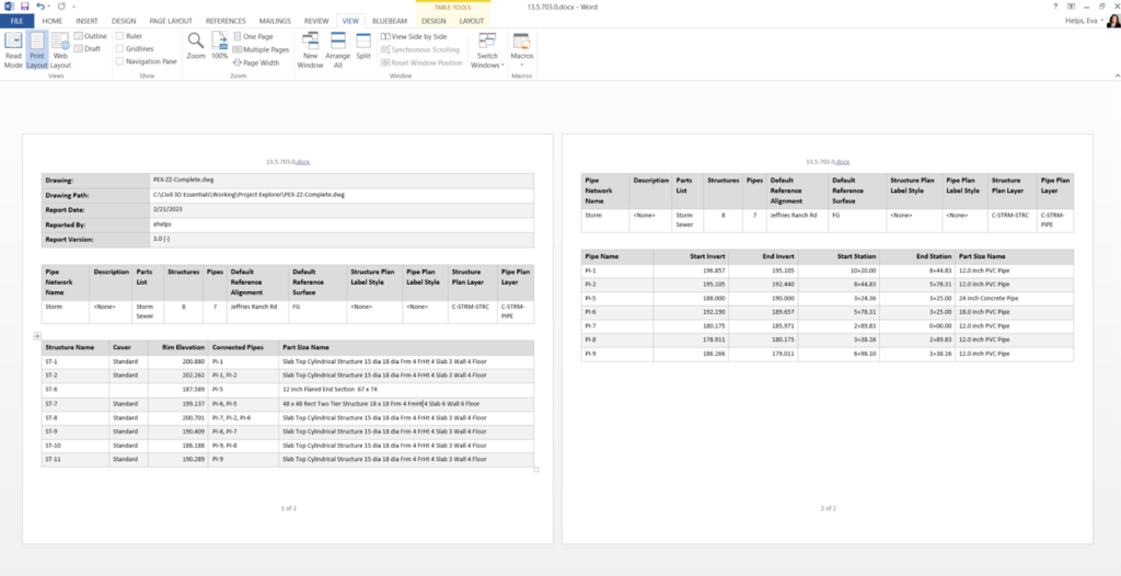
- Create the Word Document (since that is what we chose as the output file) by selecting Run Selected Action
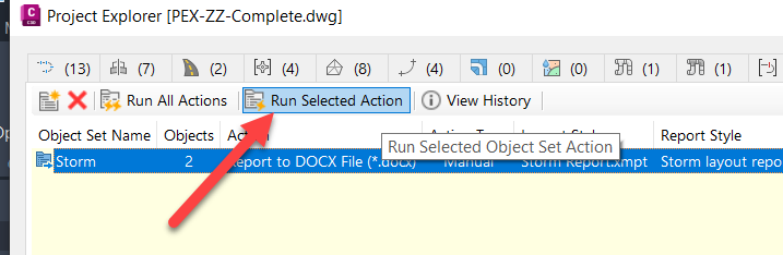
- The report created will pop up after selecting YES to view and see your Report.
Recap
- There are several different ways to create reports in Civil 3D of all the different civil objects and data, including pipe network information, to view both inside and outside of a drawing including into a pdf, csv, excel, word document, and more
- 1. Using the Pipe Network Vista, copy the structure and pipe data into an excel spreadsheet
- 2. Creating Tables of the Pipe Network information and setting up a layout tab to plot to pdf
- 3. Report Manager within the Toolbox tab in Toolspace can generate Reports to XML
- 4. Project Explorer can create customized reports using Object Sets for Pipe Network and other civil data
_____________________________________________________________________________________________
Talk To Me Goose
Feel free to let us know the good, the bad and the ugly in the comments below!
We’d love to help you learn more about how these tools can simplify and support your workflow! Reach out to us here and we can chat about your needs, company needs, or the classes we offer along with any customized training we might be able to guide you through and strengthen your business.
Have any questions about this blog or any other CAD related content? –> Email us at CADTechnical@seilerinst.com or call direct at 636-923-2662
Want more of Seiler Design Solution blogs and updates? Be the first to be notified when we send out updates or publish a blog that could have just what you’re looking for here!
If you want to get other news from Seiler Design Solutions, sign up for our Newsletter!

Leave A Comment